Bearing Temperature as Indicator of Operating Condition
Most high-speed centrifugal compressors rely on fluid film bearings-such as tilting pad journal (TPJ) bearings and equalized (Kingsbury style) thrust bearings-for rotor support and positioning. A compressor's rotor position must be maintained within a few thousandths of an inch to operate efficiently and reliably. A bearing failure will not only mean a compressor shutdown; it could also result in secondary or peripheral damage to costly internal parts. Early detection of a bearing failure may only result in an outage lasting a few days, but an undetected failure, causing major internal damage, can force an outage for weeks or months.
Condition monitoring (CM) is one of the hallmarks of a modern machinery reliability program. CM is a powerful tool that can aid in detecting early failures to better plan production outages and machine repairs. In this Compressor University, John Whalen covers a critical facet of monitoring fluid film bearings-how temperature sensors should be embedded into fluid film bearings. Heeding Mr. Whalen's advice will greatly improve the accuracy of bearing temperature measurements and consequently provide optimum machinery protection
Please send me your comments and any ideas you have for future compressor articles.
Condition monitoring has proven important in the installation and maintenance of all types of turbomachinery throughout the past 30 to 40 years. Babbitt bearing temperature is primarily important because bearings are the critical links between the rotating and stationary components in a machine. If temperatures are taken in the correct location with respect to the direction of bearing load, to direction of shaft rotation and to the distance of the tip of the sensor from the bearing running surface, then Babbitt metal temperatures can be the best indicators of a bearing's operating condition.
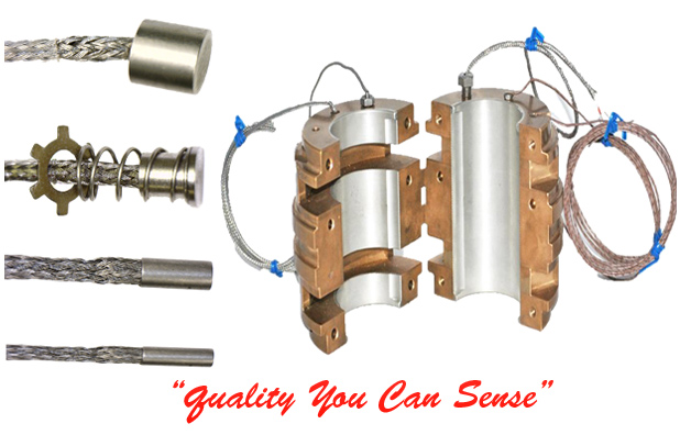
Data analysis from many bearing tests, prototype turbomachinery tests and day-to-day operation has pinpointed the locations of greatest sensitivity for installing temperature sensing probes. In most bearing applications, the current state-of-the-art technology uses some type of electrically variable tip at the end of a current conducting set of wires. The wires provide a flexible connection to the outside of the bearing while the sensor tip is engineered to the smallest practical size for insertion into the bearing.
As a practical consideration, the choice of temperature sensors has been narrowed to three basic types: Thermocouple (TC), Resistance Temperature Detector (RTD) and the Thermistor. TCs and RTDs have metal-to-metal sensing junctions and are the most popular. They can be fashioned into miniature sensing tips for ease of installation. Thermistors are ceramic semiconductors of limited use, mainly used for establishing close monitoring over a limited temperature range.
For consistency and repeatability, the 4th Edition of API 670 (2000) defined the recommended measuring points in Babbitted bearings. These locations closely approximate the zones of peak temperature as they relate to the peak hydrodynamic oil film pressure zones. These are worth repeating here for sleeve bearings, tilt pad journal bearings and tilt pad thrust bearings:
Sleeve Bearings
The probe or probes should be located 30-deg ± 10-deg beyond the point of maximum bearing load in the direction of shaft rotation. More precisely the best location is in line with the point of minimum oil film. See Notes 1 and 2 on Figure 2 for axial location of probes.
Tilting Pad Journal (TPJ) Bearings-Load on Pad
The probe or probes should be located in the pad carrying the greatest share of load, usually the bottom centerline pad. Probes should be embedded and located 75 percent of the circumferential pad length from the leading edge in the direction of rotation. For pads with self-aligning pivots, only one probe on the axial centerline is required regardless of pad length. For line contact pivots, see Notes 1 and 2 on Figure 3.
Tilting Pad Journal Bearings-Load between Pads
The probe or probes should be located in the trailing of the two loaded pads in the direction of rotation. In this pad, the probe or probes should be located 75 percent of the circumferential distance from the leading edge in the direction of rotation. For pads with self-aligning pivots, only one probe is required regardless of pad length. For line contact pivots, see Notes 1 and 2 on Figure 4.
Thrust Bearings-Tilting Pad
Probes or sensors should be located in at least two pads in the designated active thrust bearing, at the 75 percent-75 percent location, as shown in Figure 5. Regardless of the number of pads in a bearing, attempt to have sensors in two pads located in the bottom half of the bearing assembly at least 120-deg apart.
Guidelines
As a general guideline for all bearings-sleeve, tilt pad journal and thrust-probes or sensors can be installed from any direction that is most convenient from a machinery assembly standpoint as long as bearing function is not compromised and lead wires are not subjected to excessive stress, movement or fretting.
The distance of the sensor from the running surface of the Babbitt is more critical in steel and bronze than in backing material of copper because of copper's better thermal conductivity. Regardless of backing material, there is a drop in temperature from the running surface to the sensor tip as heat travels through the Babbitt layer, the backing material and the contact zone between the backing and the sensor tip.
Standardizing on sensor location will develop confidence in temperature readings. Babbitt thickness is a variable sometimes out of our control. Since we do not penetrate the bond line into the Babbitt, but stay back from the bond line by .030 to .060, the overall distance may exceed the .120 distance shown.
This article first appeared in Bearing Journal from Turbo Components & Engineering.
John K. Whalen is the engineering manager and president of TCE/Turbo Components and Engineering, Inc. in Houston, Texas. He is a registered Professional Engineer in the State of Texas and currently serves on the Texas A&M Turbomachinery Symposium Advisory Committee.
Robert Perez is the website editor for PumpCalcs.com. He has more than 25 years of rotating equipment experience in the petrochemical industry and holds a BSME from Texas A&M University in College Station, a MSME degree from the University of Texas at Austin, and a Texas PE license. Mr. Perez is also an adjunct professor at Texas A&M University-Corpus Christi, where he teaches the Engineering Technology Rotating Equipment course.
Tags: Compressors , September 2008 Issue
|